In the “Puzzle Interaction & Design Flow” post, I covered how the cubes function as puzzle elements. Here, I want to focus on how they work technically — because the cube system ended up becoming one of the parts of this project I’m most proud of.
What’s In the Cubes?
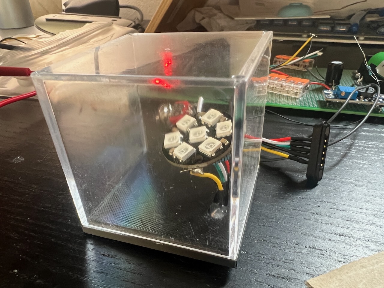
Each cube contains:
- A WS2812B 7-LED ring.
- Signal line for controlling animation and colours.
- A 480uf electrolytic capacitor.
- A mysterious resistor…
How Does the Puzzle Detect Cubes?
As the player progresses through the puzzles, the system constantly tracks which cube is inserted in which socket. How does it actually do that?
Remember that “mysterious resistor” I mentioned above? Each cube contains a different resistor in it which is connected to an ESP32 sense pin. ESP32 sense pins are analog inputs which read the voltage present on the line and convert it into ADC values in code.
Here’s a diagram showing two cubes and one socket and how each cube provides a different ADC reading due to the different resistors each one contains.
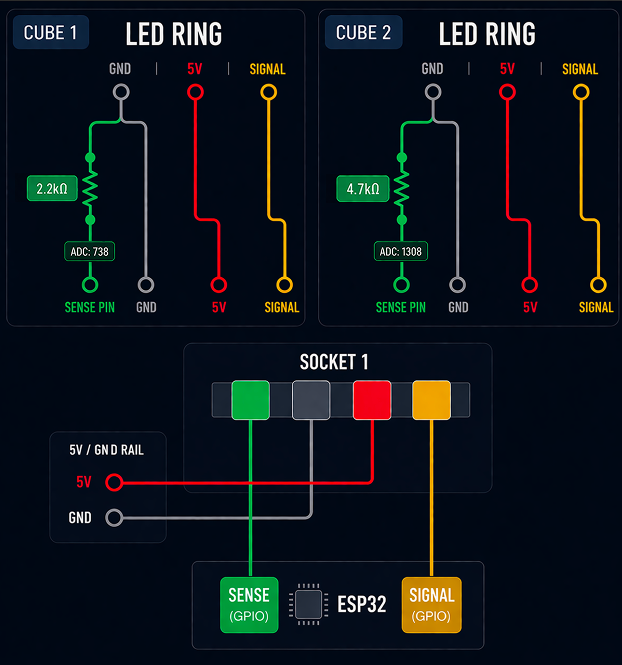
Cube 1 above contains a 2.2kΩ resistor, producing an ADC reading of roughly 700–900. Cube 2 uses a 4.7kΩ resistor, resulting in a different voltage on the sense line and therefore a different ADC reading.
This is the backbone of how most of the puzzles work and was actually one of the first ideas I had which kicked off the rest of the project. It effectively turns each cube into a uniquely identifiable component without needing any additional communication hardware.
This kind of creative hardware design was really satisfying to conceptualize and prototype before building the rest of the puzzle’s story around.
Magnetic Docking & Pogo Connectors
Once the cube internals were working, the next challenge was figuring out how to physically connect them to the main unit.
I really wanted to have an Apple Magsafe-like interaction with slotting in the cubes and snapping them out so a bit of Googling brought me to “pogo connectors”. These are spring-loaded pins which connect magnetically to a matching layout.
I 3D printed a small base to hold the pogo connector in place inside each socket, and fixed it using hot glue. The matching contacts sit in a recessed area in the cube lid.
Getting the alignment right here was important — the pins need to land cleanly on the pads without slipping or missing. After a few iterations, I found a layout that was reliable enough to work consistently.